Wiring diagram for blower motor resistor 5af72bbdca896.gif.
Jul 10, 2018 · A. adamjeeps · #3 · Jan 4, 2019 (Edited) Jeannecar said: I would like to hear from anyone who has had their blower motor for the A/C go out along with resistor wire melting. I just had this happen at 42k miles so not under way...cost is $850.00 to fix due to blower motor, resistor wire and harness plug. I was told this happens as the blower ...
SCGRANTURISMO. This could be a problem with Ground #200, which is located on the right side of the dashboard. In the diagrams down below I have included the Ground Distribution Wiring Diagram for your vehicle's Blower Motor, as well as a diagram of the location of Ground #200, and a guide for how to inspect the ground. # 1 low speed .Looking at a wiring diagram I would think that impossible . # 1 position for low speed would need to go through all the resistors in the resistor pack , which would mean all others good . # 5 high speed doesn't use resistors . uses a relay an direct B+ to the blower motor .7. 72ElCamino · #3 · Jan 15, 2009. Re: 71 blower motor resistor wiring. grumpyschevelle said: I was able to find a previos thread that mentioned the relay wiring and what wire went to what terminal blade. Im still at a loss on the wiring that goes to the blower motor resistor though.Share. Access our free Wiring Diagrams Repair Guide for GM Firebird 1967-1981 through AutoZone Rewards. These diagrams include: Fig. 1: Common wiring diagram symbols. Fig. 2: Engine control wiring schematic 1967-69 models. Fig. 3: Engine control wiring schematic 1970-71 models. Fig. 4: Engine control wiring schematic 1972 models.Nov 1, 2022 · How To Replace A Blower Motor Resistor. Find the resistance for the blower motor. Now you must unplug the resistor from the housing and take the harness off. The blower motor resistor will simply slip out of the HVAC enclosure once the wiring harness has been disconnected. The new resistor can now be installed.
Feb 4, 2022 · The most common causes for AC fan blower motor not working in Ford Fiesta are blown fuse, bad relay, resistor or control module malfunction and faulty blower motor. However, a bad electrical connector or broken wire, or a defect in the climate control unit can also cause the blower motor to stop working. 1. Wiring diagram for 1999 nissan maxima blower switch. Replaced blower motor resistor but fan for heat and ac works on high only. suspect switch is bad. would like wiring diagram for blower motor switch to test switch to verify its bad. Posted by Anonymous on Sep 17, 2014.
The most common causes for AC fan blower motor not working in Chevy Malibu are blown fuse, bad relay, resistor or control module malfunction and faulty blower motor. However, a bad electrical connector or broken wire, or a defect in the climate control unit can also cause the blower motor to stop working. 1.In most cases it's the blower motor resistor. Below is a diagram of its location, the plug and how to remove it. Looking at the picture of the plug you will want to turn the fan switch to different settings (the ones that don't work as well) and if you are geting power to each of those conections at the plug but the blower motor isn't turning on, this will be your problem.
Share. Access our free Wiring Diagrams Repair Guide for GM Firebird 1967-1981 through AutoZone Rewards. These diagrams include: Fig. 1: Common wiring diagram symbols. Fig. 2: Engine control wiring schematic 1967-69 models. Fig. 3: Engine control wiring schematic 1970-71 models. Fig. 4: Engine control wiring schematic 1972 models. Blower Motor Resistor Wiring Diagram. A wiring diagram will show you where the cables should be connected, removing the need for guesswork. You can avoid making errors if you use a wiring diagram to discover out what wires go where.8.9K subscribers Subscribe 1.6K views 2 years ago how to diagnose fan motor from wiring diagram with blower resistor Network this explains all of the speeds of the fan motor and how the...Apr 15, 2008 · Re: heat/AC wiring diagram. « Reply #6 on: April 16, 2008, 03:44:37 PM ». ok heres the diagram you posted. the brown/white wire from the selector to the resistor is yellow on my truck. this wire has power all the time even when the truck is off and when the fan is in the off position which feeds the fan 12V and 1 amp (motor does not operate ... No, the resistor will easily come off and rep-connect. Just trace the red/back from the resistor and you'll find it plugs into the fan motor. That is the easiest part of this repair, the splicing of wires is the hardest. As smith mentioned, pay attention to the wire order so you don't do what I did first.
OPGI has pictures of both the three-prong blower motor resistor for 1968 with AC # CH31821 ($25) and the four-prong blower motor resistor for 1969-72 with AC # CH31592 ($46) -Frank. 1970 Chevelle Malibu purchased new in 1970. 355 SBC, XE262H cam, Performer RPM heads, MSD HEI, TH200-4R trans, 3.55:1 Posi, digital gauges, QA1 coilovers.
Aug 14, 2019 · The kit that Toyota recommends is 87138-04070 (resistor) and wiring adapter (82141-04Q80). This resistor has the terminals in a square pattern rather than a line. I'm assuming this is from a 3rd gen and hopefully changes were made to fix the well known issue.
Dec 16, 2013 · sounds like the drivers temp door actuator is not working should be located on the drivers side of the air box down by the gas pedal or center dash area. Electrical Problem 1994 Buick Lesabre. GM usually puts the Fuse Diagram in the Back of the Owners Manual. cruise control won't work, 10 amp. fuse in fuse box under hood ok. Jun 6, 2009 · How to test the heater fan switch 2005 dodge caravan. On a Chrysler product, the blower switch and resistor provides the ground circuit for the blower motor. The highest speed circuit which is dark blue and gray goes thru the resistor directly to the fan switch. The other speeds go thru the resistor to slow down the motor. Once you have the right diagram, follow these steps to install it: 1) remove the old resistor 2) disconnect the wire harness. 3) connect the new resistor 4) reinstall the wire harness 5) test the new resistor by turning on the blower motor. If it works, you’re all set!Blower Motor Resistor Wiring Diagrams. A blower motor resistor works by routing power through 1, 2, or 3 in-series resistors. See the blower motor resistor wiring diagrams below to see how it works on each speed. Posted on June 26, 2020 by Rick Muscoplat. eautorepair.net.Oct 1, 2020 · Just replaced blower motor resistor to fix fan not coming on. How to test the blower motor resistor 2001 2004 dakota durango. You ll notice that the blower motor is a simple 2 wire component. Dodge was founded in 1914. Variety of 2002 dodge dakota wiring diagram. Cómo probar el motor del soplador 2001 2003 dodge dakota and durango at. Jul 10, 2008 · Blown heater motor resister, melted speed switch, melted wires in steering column. The Fix: Adding relays in the heater circuit. You will also need to replace your blower motor resistor, and selector switch if you have not already done so. Parts Needed: 4 relays. 10 feet red 12 gauge wire.
Testing the voltage at the blower motor. If there is a voltage at the motor (at least 4-6 Volt at low speed and 12 Volt at high speed), but the motor doesn't run, the motor is bad. Things like leaves, twigs, nuts, pieces of a ripped cabin filter can jam the blade of the blower motor. This happens often in many cars.SCGRANTURISMO. This could be a problem with Ground #200, which is located on the right side of the dashboard. In the diagrams down below I have included the Ground Distribution Wiring Diagram for your vehicle's Blower Motor, as well as a diagram of the location of Ground #200, and a guide for how to inspect the ground.Aug 3, 2023 · Figure 1 If your blower or fan motor runs at full speed regardless of the setting you have it on there is a very good chance your resistor is bad. The resistor is located below the blower motor in the cabin air box (red arrow). Please see our article on blower motor replacement for additional assistance on removing the motor. Sep 17, 2014 · Wiring diagram for 1999 nissan maxima blower switch. Replaced blower motor resistor but fan for heat and ac works on high only. suspect switch is bad. would like wiring diagram for blower motor switch to test switch to verify its bad. Posted by Anonymous on Sep 17, 2014. A. adamjeeps · #3 · Jan 4, 2019 (Edited) Jeannecar said: I would like to hear from anyone who has had their blower motor for the A/C go out along with resistor wire melting. I just had this happen at 42k miles so not under way...cost is $850.00 to fix due to blower motor, resistor wire and harness plug. I was told this happens as the blower ...BLOWER RESISTOR BLOCK WIRING DIAGRAM (NEGATIVE SWITCH CONTROL)Sa video na ito ay ipapakita ko sa inyo ang wiring diagram ng blower resistor block. Kaya't pan...OPGI has pictures of both the three-prong blower motor resistor for 1968 with AC # CH31821 ($25) and the four-prong blower motor resistor for 1969-72 with AC # CH31592 ($46) -Frank. 1970 Chevelle Malibu purchased new in 1970. 355 SBC, XE262H cam, Performer RPM heads, MSD HEI, TH200-4R trans, 3.55:1 Posi, digital gauges, QA1 coilovers.
It seems, too, that the black ground wire on the blower motor (accessible from just below the dash) has NO ground potential. I ghetto jumpered a 16 gauge wire from the back of the metal clip on the ground wire to the dashboard impact bar/brace and the fan turns at variable speeds with the knob! All positions of "on" work - low, medium, high ...
Aug 28, 2020 · looking at diagram 68/69 diagram ( 70 maybe the same ? ), High speed is a straight feed from the switch not going through the resistor block, just like 71/74 are. Its spliced into the resistor block just to use that wire to source the output from resistor block to the blower with the speed selected using just one wire for the blower. Jeep Master. 21,873 Answers. Well, not exactly. The blower switch gets power from the control panel that gets power from the 25amp fuse in the fuse box. The wire from the fuse box to the control panel is black and tan, the wire from the control panel to the fan switch is yellow and brown. Posted on Aug 24, 2012.See full list on ricksfreeautorepairadvice.com Jul 13, 2023 · Slide it toward the rear of the vehicle to remove it. Figure 3 The green arrow points to the blower motor resistor and the red arrow points to the blower motor. All testing will be performed at the resistor. Figure 4 Start by connecting your DVOM to the power feed. Connect your red lead to terminal 4. 4. Remove the 2 screws that secure the blower motor resistor or controller to the heater-AC housing. 5. Remove the blower motor resistor or controller from the heater AC housing. INSTALLATION 1. Install the blower motor resistor or controller to the heater AC housing. The housing is indexed to allow (controller power module) mounting in only oneso i have replaced the resistor and wiring harness and ac worked great for 3 days, now nothing. i replaced the blower motor and still nothing. i am showing 12-15v at each fan setting, 0v through the ground, and 12-15v from the resistor to the blower motor through the black wire. all fuses are appear to be ok and i am at a loss.Nov 11, 2008 · If the same as on a 93 the wiper motor has two connectors. Connector A (motor): wiper switch to motor (high) - dark brown / orange. wiper switch to motor (low) - white. ground - black. Connector B (park switch): wiper switch to motor (park and return) - red. wiper switch to motor (park return) - black. ground - black. There is a plug in jumper harness avaliable for installing a later model blower motor into an earlier 1992-2004 car, part #4W7Z-14A411-B (WT-56853). You could also cut off your old wiring pigtail and splice on a new one using kit 3U2Z-14S411-YBA (WPT-605) instead.
Blower resistors are resistors which are used to control the fan speed of automotive blowers. The fan speed can be changed either by switching the blower resistor resistance mechanically using a rotating lever, or electronically by the air conditioning system. The change in resistance then limits the current through the motor, which dictates ...
Nov 2, 2015 · On a 66 heater (no ac car) the blower fan power is fed via the orange wire from the heater motor. That wire goes back through the bulkhead connector, so check and clean that connection. From there it goes to the heater blower resistor, inside the car, on top of the heater box under the glove box.
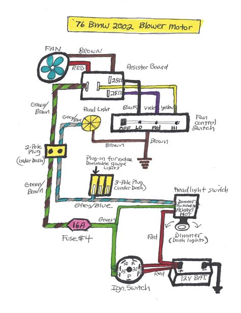
Thanks again. I do have the 1972 wiring diagram. I cant seem to figure out what goes in between the fan switch and the resistor. It looks like: Switch side 14 brn-----from fuse 18 y-----to resistor 16 lbl-----to resistor 18 or-----to resistor 14 or-----to blower If I could figure out which pins to hook from the resistor to the switch, I could probably just rig it up, and not worry about ...8.9K subscribers Subscribe 1.6K views 2 years ago how to diagnose fan motor from wiring diagram with blower resistor Network this explains all of the speeds of the fan motor and how the...Mar 21, 2010 · Hooked the brown wire to the positive battery terminal, the yellow to the negative, I heard the fan spin- so, the fan blower is operational. Step 2. If that works reconnect them. Turn the ignition on. Take the wire, should be yellow, off of the resister on the heater box and ground it. The fan should also spin. The blower motor consists of the blower fan and motor. A sirocco fan has been adopted for the blower fan. Operation. 1. The front body control module (FBCM) turns on the blower relay based on the blower ON signal sent from the climate control unit. 2. When the blower relay turns on, the blower motor fan rotates. 3. The rotation speed of the ...Buy Now!New Blower Motor Resistor from 1AAuto.com http://1aau.to/ib/1AHBR00086The heat and air condition fan is controlled by a separate module, called the b...A failed blower motor resistor can cause issues with the operation of the entire heating and air conditioning system. Usually a bad or failing blower motor resistor will produce a few symptoms that can alert the driver of a potential issue. 1. Blower motor stuck on one speed. A common symptom of a faulty blower motor resistor is a blower motor ...Dec 27, 2014 · # 1 low speed .Looking at a wiring diagram I would think that impossible . # 1 position for low speed would need to go through all the resistors in the resistor pack , which would mean all others good . # 5 high speed doesn't use resistors . uses a relay an direct B+ to the blower motor . The blower motor consists of the blower fan and motor. A sirocco fan has been adopted for the blower fan. Operation. 1. The front body control module (FBCM) turns on the blower relay based on the blower ON signal sent from the climate control unit. 2. When the blower relay turns on, the blower motor fan rotates. 3. The rotation speed of the ...
The blower motor consists of the blower fan and motor. A sirocco fan has been adopted for the blower fan. Operation. 1. The front body control module (FBCM) turns on the blower relay based on the blower ON signal sent from the climate control unit. 2. When the blower relay turns on, the blower motor fan rotates. 3. The rotation speed of the ...blower motor issue. I have 2007 colorado 4x4 crew cab with 5 cylinder. My heater/ac blower motor does not work on any of the settings. I removed the wire from the splice pack and cleaned it up box next the air filter and put a connector and bolted to the fender. I replaced the resistor, replaced the wiring harness, and replaced the blower motor.Jan 14, 2009 · 7. 72ElCamino · #3 · Jan 15, 2009. Re: 71 blower motor resistor wiring. grumpyschevelle said: I was able to find a previos thread that mentioned the relay wiring and what wire went to what terminal blade. Im still at a loss on the wiring that goes to the blower motor resistor though. Instagram:https://instagram. candc oilfield serviceskobalt kst 140xb 06 replacement headaccident on i 8 today san diegominnesota attorney general contact 3Ø WIRING DIAGRAMS 1Ø WIRING DIAGRAMS Diagram ER9 M 3~ 1 5 9 3 7 11 Low Speed High Speed U1 V1 W1 W2 U2 V2 TK TK Thermal Overloads TWO SPEED STAR/DELTA MOTOR Switch M 3~ 0-10V 20V 415V AC 4-20mA Outp uts Diagram IC2 M 1~ 240V AC 0-10V Outp ut Diagram IC3 M 1~ 0-10V 4-20mA 240V AC Outp uts These diagrams are current at the time of publication ...Jun 1, 2013 · In most cases it's the blower motor resistor. Below is a diagram of its location, the plug and how to remove it. Looking at the picture of the plug you will want to turn the fan switch to different settings (the ones that don't work as well) and if you are geting power to each of those conections at the plug but the blower motor isn't turning on, this will be your problem. wide linen blend trousersatandt internet outage dallas Version. Listed below is the vehicle specific wiring diagram for your car alarm, remote starter or keyless entry installation into your 1998-2001 Dodge Ram . This information outlines the wires location, color and polarity to help you identify the proper connection spots in the vehicle. Please be sure to test all of your wires with a digital ... ray ban repairs near me Version. Listed below is the vehicle specific wiring diagram for your car alarm, remote starter or keyless entry installation into your 1998-2001 Dodge Ram . This information outlines the wires location, color and polarity to help you identify the proper connection spots in the vehicle. Please be sure to test all of your wires with a digital ... A. adamjeeps · #3 · Jan 4, 2019 (Edited) Jeannecar said: I would like to hear from anyone who has had their blower motor for the A/C go out along with resistor wire melting. I just had this happen at 42k miles so not under way...cost is $850.00 to fix due to blower motor, resistor wire and harness plug. I was told this happens as the blower ...